Let's talk about a stabilized(?) power supply for HAM use. 13.8 Volt / 0-30 amps.
A very popular power supply is the EP-925. It is sold under several 'makes' but they all look the same.
I had one for many years but I was not impressed by its stability. I saw the voltage needle swing during my SSB QSO.
A drop of 0.8V or more was normal. An instable power supply on a transmitter results in a distorted signal (SSB).
I took the diagram from the web and studied it. Also did some measurements.
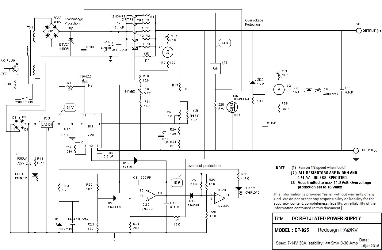
Below the original diagram.
Diagram of redesigned power supply.
Weaknesses and what I've changed:
The 723 voltage regulator is powered from a separate secondary tap on the transformer. Purpose: a stable source.
Due to the inferior quality of the transformer the voltage on this tap varies considerably under the influence of the load on the main secondary tap and the current through the primary tap.
To solve this, I added an extra stabilizer uA7824 (IC3) to give the 723 a stable source. In my EP-925 C17 was missing. I added C17, 100nF.
The 7824 should be mounted on the heat-sink.
The circuit around the 723 could be improved on some points.
TR6, NPN TIP31C is replaced by a PNP TIP42C. This design makes use of the Hfe of TR6 to add more stabilization.
(Print track interrupted under 723. Pnt.12 = V+ on 7824, pnt.11 = Vc to base TIP42C and pnt.10 = Vout to collector of TIP42C.
R6 = 330 Ohm and R7 = 680 Ohm.)
The inputs of the 723 were set up for lower output voltages (up to 9 volts).
I chose 13.8 volts and adjusted the input setting accordingly. R14 to 680 ohms. Parts removed: R15, R16, D13 and D? on pnt.1.
Input pnt.4 changed (R16 bridged) and additional resistor (R13.8) parallel VR3 (output voltage) in order to limit the maximum output voltage to 14.0 volts.
I never understood the circuit around the fan. One thermostat, two opamps and one transistor to turn a fan on and off?
The thermostat used, is an NC type (normally closed). Maybe that's why they came up with this weird design. Anyway, I dropped it.
The thermostat has been replaced by an NO type (normally open) that directly switches the fan. Parallel to the thermostat a resistor of 220 Ohm / 5 Watt is connected which makes the fan run quietly at half speed. All other parts belonging to the fan have been removed.
The heat-sink is continuously cooled and I have not yet noticed that the thermostat set the fan at full speed.
Fan replaced by a quiet PAPST 8414NG, mounted blowing outwards.
This offers additional noise reduction.
On idle (half speed) even not noticeable.
I taped the top openings of the hood. The cool air is now drawn in at the sides and flows along the heatsink to the rear.
Over-voltage protection. (*)
The maximum output voltage is limited to 14.0 volts.
I added a surge protector of +/- 16 volts.
Thyristor BTV24 / 1400R connected in parallel with the bridge rectifier (replaced by a 50A / 120V type) is controlled
by ZD2 and R 100 Ohm sensing the output.
When over-voltage occurs, the thyristor will short circuit the rectifier DC output which will cause the fuse to blow.
(*) This is a simple but not so neat protector.
Damage on the rectifier is not unthinkable.
In one occasion the fuse broke when turning on the power, but after replacing the fuse all was OK.
The fuse is a S-type (slow) because it has to handle the switch-on current surge.
I'm thinking about a 'slow start' update so the fuse can be replaced by a lower amp F-type (fast).
This would prevent an accidental activation of the over-voltage protection and spares the rectifier when there is an over-voltage situation.
!!! For this overhaul several board tracks have to be cut, parts replaced, added or removed. It's not a novice job!
Results. Measured direct at the output, the voltage varies less than 5 mV between minimum and maximum load. No noise.
Now I can use my K3 with full power without being distracted by a dancing voltage needle. :-)
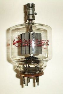
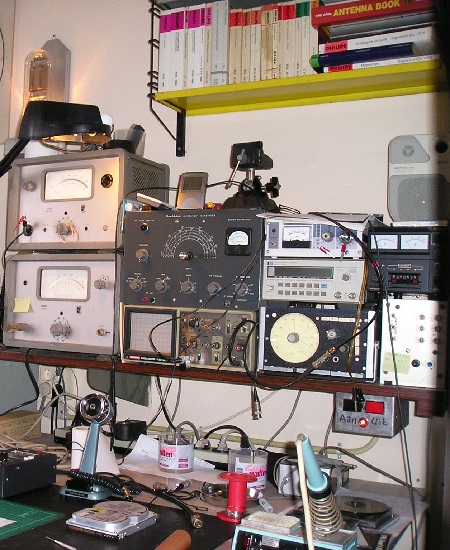
My 'workshop'.... Eimac 3-500Z